
This is your website preview.
Currently it only shows your basic business info. Start adding relevant business details such as description, images and products or services to gain your customers attention by using Boost 360 android app / iOS App / web portal.
Manufacturing test
Home  Products


Turbocharger Sales and Service
VIEW DETAILS
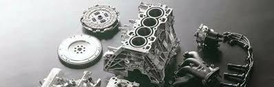
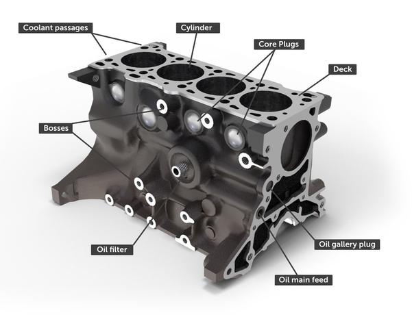
Engine Reconditioning
VIEW DETAILS
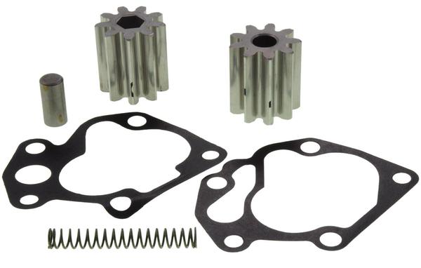
Oil Pump Overhauling
VIEW DETAILS
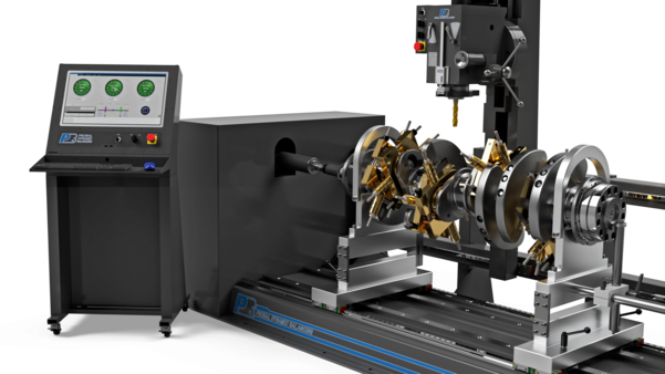
Crankshaft Dynamic Balancing
VIEW DETAILS
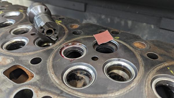
Cylinder Head and Block Pressure Testi
VIEW DETAILS
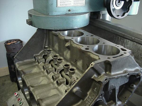
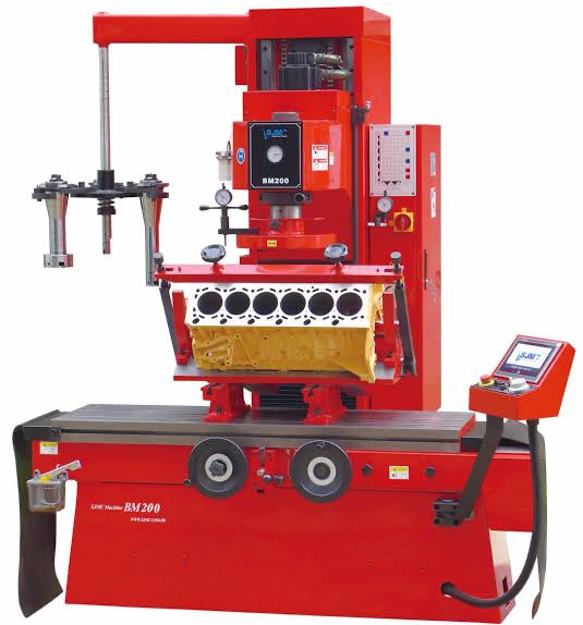
Cylinder Head and Block Resurfacing
VIEW DETAILS
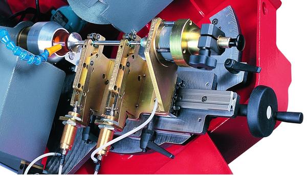
Valve Resurfacing
VIEW DETAILS
Valve Seat Cutting
VIEW DETAILS
Connecting Rod Boring and Grinding
VIEW DETAILS
Cylinder Line Boring and Honing
VIEW DETAILS

Cylinder Liner Replacement
VIEW DETAILS
Filter using tags